Tuesday, August 21, 2007

Pigtail Trouble With Speakers - How to Handle Them

The Speaker Pigtail


A pigtail is that part that connects the speaker voice coil to the terminal log where the speaker wires is located. The pigtail is what you see usually hanging from the terminals of the speaker going to the center of the speaker cones where the voice coil is located.

Diagnosing Speaker Problems With Pigtail


A pigtail problem with speakers have the same trouble occurrence as that of which you have a dead set or no sound in your speakers. Usually, if the pigtail is causing the trouble, you would most likely have no sound and sometimes an intermittent sound. you can only know if what's causing th intermittent trouble is th pigtail if you try and pull the pigtail a little bit to cause the corroded portion to make a little contact to the voice coil and the speakers sounds normal afterwards.

Corroded Pigtail can Cause a Dead Speaker


The corrosion in the pigtail is that which looks like some carbon deposit or coal like coating in the copper colored pigtail. If you see this in your speaker pigtails, then it is most likely that it is defective or if not yet, wait for a week or two and you'll see the effects of this in intermittent sound or on and off sound especially if the music is too loud. You can also try and push a little bit, the cones of your speaker and let it come back to its normal position while repeating the process and if the sound comes back and disappears again, then you have the pigtail trouble.

Pigtail Trouble Remedy


The only remedy to this type of trouble is to replace the pigtails with a new one. In replacing this part of the speaker, be sure to use a small cloth in holding the copper pigtail because any sweat from the hands or fingers will cause it to corrode in a shorter time possible than avoiding your hand from touching the copper pigtail. If this occurs be sure to wash the pigtails with a little lacquer thinner using a small cloth. Don't overdo it or it will cause the cones to deteriorate earlier than expected. After the repairs, be sure to put some white epoxy to the base of the pigtail to avoid it from corroding again and this will also serve as a stronghold for the speaker cones and also acts as a preventive to the carbonizing and lessening the defects in pigtail in the future.

Saturday, August 4, 2007

Free Web Hosting for Your Own Domain

Web Free Hosting is Offering Free Web Hosting Services


We are currently offering free web hosting. For those who are interested in getting a slot on our list, please visit Web Free Hosting and you will find out about the details of the free web hosting offer. Or you can try and see some of the amenities below.

We offer absolutely free, professional web hosting services with the following features;

  • 50MB Disk space
  • 1GB Monthly bandwidth
  • Free CPanel with Fantastico
  • Unlimited email addresses (example@example.com)
  • Unlimited subdomains
  • Popular scripts included in Fantastico
    • WordPress 2.2.1
    • phpBB2
    • Coppermine Photo Gallery
  • Many more!

When you sign up for your free web hosting account, you would also be receiving free SEO analysis and recommendation for you website along with free manual directory submission to over 2,000 free web directories.

Hurry!!! sign up now your domains for a different experience.

Monday, April 16, 2007

Array Resistors

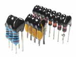
sip resistor network mixed resistor networksip isolated resistor arrayepoxy dipped mixed array
resistor array displays in SIP package

image source is from: www.reliablelectronics.com/images/SIP_Iso_Res...

Array Resistors - Array resistors are specifically just a combination of resistors made and compacted into one package for the purpose of containing a single composition of series of resistors but of multiple uses and functions to add functionality to the circuit boards where you can use it on many purposes as intended. Sometimes the array resistors are called as array chips and sometimes chip resistors or its combination, the chip array resistors. Some manufacturers and suppliers have it labeled as the (BGA) or ball grid array. Common sources and manufacturers come from either China, Taiwan or India because of the low labor costs and cheap raw materials to use and adapt for the array resistor manufacturing. These array resistors also come in two different packages such as the SIP and DIP package. Each of this array resistor package serves its purpose and use depending upon the need of the circuit board design and component placement.

dip array network
resistor array display in DIP package

image source is from: www.reliablelectronics.com/images/Hm_Pg_Dip_A...

An article from wikipedia about the relevance of BGA's is discussed here - http://en.wikipedia.org/wiki/Ball_grid_array

Advantages

High density

The BGA is a solution to the problem of producing a miniature package for an integrated circuit with many hundreds of pins. Pin grid arrays and dual-in-line surface mount (SOIC) packages were being produced with more and more pins, and with decreasing spacing between the pins, but this was causing difficulties for the soldering process. As package pins got closer together, the danger of accidentally bridging adjacent pins with solder grew. BGAs do not have this problem, because the solder is factory-applied to the package in exactly the right amount.

Heat Conduction

A further advantage of BGA packages over packages with discrete leads (i.e. packages with legs) is the lower thermal resistance between the package and the PCB. This allows heat generated by the integrated circuit inside the package to flow more easily to the PCB, preventing the chip from overheating.

Low Inductance leads

The shorter an electrical conductor, the lower its inductance, a property which causes unwanted distortion of signals in high-speed electronic circuits. BGAs, with their very short distance between the package and the PCB, have low inductances and therefore have far superior electrical performance to leaded devices.

BGAs find some use in security-sensitive applications, especially where it is impossible to prevent physical access to the chip. For instance, a ROM chip with a BGA configuration is considerably more difficult to access than one in a DIP or TSOP layout. Tracing circuit paths to the BGA chip is limited by the contact points being obscured by the chip itself.

Disadvantages

X-ray of BGA.
X-ray of BGA.

Non compliant leads

A disadvantage of BGAs, however, is that the solder balls cannot flex (non-compliant) in the way that longer leads can. Bending, due to a difference in Coefficient of thermal expansion between PCB substrate & BGA (thermal stress), or flexing & vibration (mechanical stress) can cause the solder joints to fracture. BGAs are therefore unpopular in certain fields, such as aerospace and military electronics. This problem can be overcome, at a cost, by matching the mechanical and thermal characteristics of the PCB to those of the BGA.

Expensive inspection

Another disadvantage of BGAs is that, once the package is soldered down, it is very difficult to look for soldering faults. X-ray machines and special microscopes have been developed to overcome this problem, but are expensive. If a BGA is found to be badly soldered, it can be removed in a rework station, which is a jig fitted with infrared lamp (or hot air), a thermocouple and a vacuum device for lifting the package. The BGA can be replaced with a new one, or can be refurbished or reballed. Packets of tiny ready-made solder balls are sold for this purpose.

Friday, February 16, 2007

Using Service Modes and Service Manuals

Most service manuals or service modes repair tips are very useful these days especially if you are very inclined to repair of the digital age electronics system. Almost all brands of electronics appliances and gadgets are equipped with service mode guides that the service technician can use for repairing troubles that are specified in the manual itself. In a revolutionary world or the repair industry in electronics, it is important that service technicians keep themselves up to date when matters of repair are on the table.

There different brands that you can delve yourself and update your knowledge upon ranging with different brand names like what I will be listing below.

  • Sony Service Manual
  • Sharp Service Manual
  • Sanyo Service Manual
  • Hitachi Service Manual
  • TCL Service Manual
  • Goldstar Service Manual
  • Nipponstar Service Manual
  • JVC Service Manual
  • Samsung Service Manual
  • Toshiba Service Manual
  • Sears Service Manual
  • Polytron Service Manual
  • Promac Service Manual
  • Philips Service Manual
  • RCA Service Manual
  • LG Service Manual
  • Panasonic Service Manual
  • Daewoo Service Manual
  • Visio Service Manual

Each of this television brands have their own unique TV manuals as specified and I will be providing details later in my coming updates.

Wednesday, February 14, 2007

Basic PC Troubleshooting - Beeping Sound Trouble


Beeping Sound Troubleshooting:

When you encounter a beeping sound trouble in your PCs, first thing that comes into your mind is that you need to let an expert see what's wrong in your PC. Wrong choice i would say because if you are having troubles in your PC with the same instance as what i am describing in this post. Here are some basic but most often useful tips that i believe may help you out with what you have been experiencing.

  1. Try first to open the case but make sure that the PC AC cord or plug is unplugged in the 220-volt line or if you are using a transformer, unplug your PC from there.
  2. See if too much dust has accumulated in the mother board which is the only parts board i you can see inside. Remove the dust using a small paint brush but be sure to gently do it especially if you are to remove dust from the main board itself.
  3. When you see clearly that the main board and the wires are cleared of dust, try to remove the memory card first and be sure to remember the correct place or slot of its original placement.
  4. Re- place or put again the memory card after cleaning the contact point which is the copper side colored like a gold and try rubbing it with an ordinary eraser in its terminals.
  5. Avoid touching the terminals after cleaning it or it may cause loose contacts and be sure to re- plug it tightly in its original position.
After doing the procedure stated above, try and plug the unit to the AC line (220 Volt) or transformer if you are using one. If what you have done did not cure the trouble, don't worry because we still have many more to important things to do aside from the above mentioned procedures.

Be sure to again remove the plug from the AC line (220 volts) or transformer if you are using one before we proceed to the next step.

The Power Supply Approach:

  1. Next step to do is to remove the power supply plug from the terminal jack where it is plugged in the mother board and see for some dust that has accumulated for the years that you haven't been doing the regular maintenance of cleaning the mother board.
  2. Remove the dust using again the small paint brush that you used in the first procedures above.
  3. Re-plug the power supply and be sure that it fits well slots provided for it in the mother board power supply jacks.
  4. Apply just enough force in plugging it back and see to it that the line in the power supply jacks meets with the line in the mother board jacks.
  5. The power supply plugs have locks that should be well secured on the other end of the jacks in the mother board. Be sure that they fit well or it may cause even more trouble to your PC.
When all else fails using these procedures that i have provided you, i bet you really need a more professional approach to the problem that you are encountering. This may take either seeking the advice of a qualified PC serviceman or replacing the needed parts and buying a new replacement part for your PC. You can also try logging in or registering to some PC guides and troubleshooting forums.